 |
 |
 |
 |
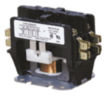
2 POLE MAGNETIC CONTACTOR
Magnetic contactors are standard in all duct heaters. They are used for primary or back-up control. UL approved for 250,000 cycle operation. |
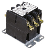
3 POLE MAGNETIC CONTACTOR
Magnetic contactors are standard in all duct heaters. They are used for primary or back-up control. UL approved for 250,000 cycle operation. |
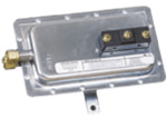
AIR FLOW SWITCH
Prevents heater from being energized when the fan is not on. Non adjustable airflow switch (shown) requires a minimum of .07”WC pressure. Adjustable airflow switch available with rating of .05” ± .02” WC to 12”WC. |
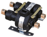
2 POLE MERCURY CONTACTOR
Recommended where noise levels are of concern. Contacts are made and broken between two pools of mercury, separated by a ceramic insulator. Design ensures clean snap action, no chatter and little contact arcing. Position sensitive. Must specify horizontal or vertical air flow. UL listed for 250,000 cycle operation. Not available on bottom mount heaters. |
|
 |
 |
 |
 |
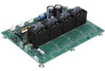
ELECTRONIC STEP CONTROLLER
Provides electronic sequencing control of an electric duct heater up to 12 steps. When interruption of power occurs all the stages will recycle to off then and upon the restoring of power, re-energize the switches in a stepping sequence. Commonly used with a 2–10 vDC from a stand alone
T-stat, 2-10 vDC from a DDC building automation system and 4-20 ma from a building automation system; check with the factory for availability. Not available on Models ADH-R6,8,10 or bottom mount heaters. |
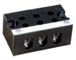
TERMINAL BLOCK
High voltage terminal blocks are sized for copper conductors only. Sized to accept up to 500 MCM line feeder per pole. Heaters requiring feeders greater than 500 MCM will be supplied with main power terminal blocks which will accept two (2) parallel feeders up to 500 MCM each per pole. Low voltage control circuit terminal boards are included for ease of field connection. |
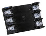
FUSE BLOCK
3-Position fuse block |
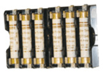
POWER FUSING
UL standards and NEC code required for heaters drawing more than 48 AMPS. Accessory fusing is available on heaters drawing less than 48 AMPS when requested |
|
 |
 |
 |
 |
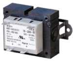
CONTROL TRANSFORMER
Utilized when control voltage differs from line voltage. Primary over current protection. Class 1 units must have primary side protection by fusing. Class 2 units have internal protection and do not require additional fusing unless specified |
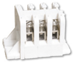
MAIN POWER TERMINAL BLOCK
High voltage terminal blocks are sized for copper conductors only. Sized to accept parallel feeders up to 500 MCM each per pole. Low voltage control circuit terminal boards are included for ease of field connection. |
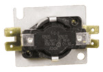
TIME DELAY RELAY
Relays provide a time delay of 30 to 60 seconds when energizing or de-energizing the circuit controlled. Standard control voltages of 24 through 277. |
PILOT LIGHT
Side panel installation for indicating the following heater conditions: heater energized, step energized and air flow switch open. Pilot light control voltages must be 24 or 120 volts. |
|
 |
 |
 |
|
PRESSURE ELECTRIC (PE) SWITCH
Provide an interlock when basic control system is pneumatic. Wired to close on pressure rise. Not factory set. Will require field adjustments to specific job requirements. |
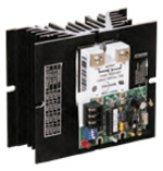
SOLID STATE RELAY (SSR)
Solid state relays (SSRs) provide the finest in electric duct heater control. 100% Solid state stepless modulation. Noiseless. Power and heat output precision. Not available on Models ADH-R6,8,10 or bottom mount heaters. |
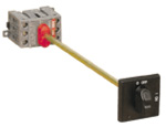
DISCONNECT SWITCH
Available unfused door interlocking disconnect switch (max. 384 AMPS). Not available on bottom mount heaters. |
|

